Phosphorous ore is dissolved in the sulfuric acid that is produced in the Outotec Sulfuric Acid Plant, treating the off-gases from the Outotec Pyrite Roasting process. The phosphoric acid is then further treated to produce fertilizers. The calcine from the roaster is further treated in the Outotec Calcine Leaching Plant, where considerable amounts of cobalt, copper, zinc, gold, and silver are recovered from the calcine using several Outotec hydrometallurgical processes and pieces of proprietary equipment.
Dec 11, 2019
Calcine pressure leaching – Eti Bakir case study
Outotec has developed a processing concept for the comminution of phosphorous ore, for the ETI Bakir A.S. fertilizer plant in Turkey, Mardin Province, near the border with Syria.
Figure 1. Plant location
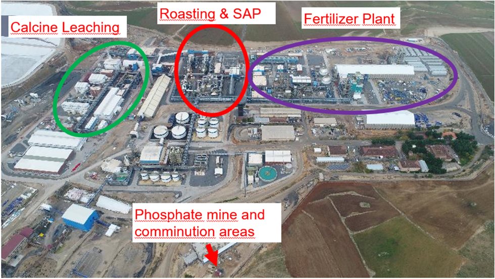
Figure 2. Process area
Development of the calcine leaching process was carried out in the Outotec Research Center in Pori, on the west coast of Finland, during 2013–2014. Plant construction work started in early 2015 and the first calcine leaching plant equipment was installed in early 2016. Cold commissioning was started in March 2018 while some of the installation work was still going on. The hot commissioning period started in September 2018 and capacity ramp up was carried out in the first half of 2019. By the end of Q3 2019 nameplate capacity had been reached and the product quality was at design values. The metal production levels are 1990 tpa copper in cathode, 3100 tpa cobalt in cobalt carbonate, and 860 tpa zinc in zinc carbonate.
The pyrite concentrate feed to the roasters is designed to be 500,000 t/a and the calcine feed rate from the roaster to the calcine leaching plant is 375,000 t/a. The calcine leaching plant process starts with calcine pulping and then leaching in an autoclave under elevated temperatures, oxygen overpressure, and acid conditions. The autoclave itself is continuously operated, brick lined, and with five compartments that each have a separate agitator. The maximum operating conditions for the autoclave are 2,900 kPa(g) pressure, around 220°C temperature, and free acid concentration of 30–80 g/L. High-pressure steam and oxygen are injected into the autoclave during operation. The autoclave process also includes a two-stage energy recovery system and a vent-gas scrubbing system. The main process connection of the calcine leaching plant process is presented in Figure 3.
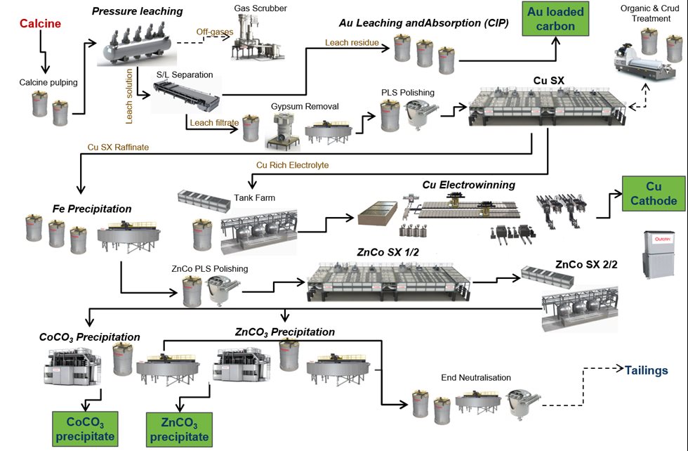
Figure 3. Showcase of our technology
After the autoclave the leach residue is filtered and sent to the gold and silver recovery steps. The pregnant leach solution (PLS) containing the dissolved copper, cobalt, and zinc is pumped to the polishing filters before copper solvent extraction and electrowinning. The process comprises three extraction stages, one washing stage, and two stripping stages. LIX is used as an extraction reagent in the CuSX process. To remove any remaining organic entrainment from the electrolyte, there is also an after-settler and dual media filters before the electrolyte circulation tanks. Copper is recovered with electrowinning as LME A-Grade copper cathodes.
After CuSX and EW, there is an iron-removal process after which the solution is filtered and then fed to zinc and cobalt solvent extraction (ZnCoSX). Cyanex 272 is used as an extraction reagent in ZnCoSX. Two separate product solutions are produced in the ZnCoSX process: Co solution and Zn sulfate solution. The Co solution is sent for final copper removal before cobalt precipitation. Copper removal from the Co solution is performed in fully automatic ion exchange (IX) columns, which are designed to remove the final remaining traces of copper.
In the final product stage, cobalt and zinc are precipitated as separate metal carbonate salts using sodium carbonate. A bleed stream of extracted solution from the ZnCoSX process and solutions from the Co and Zn precipitations are sent to final neutralization, and the solution is then directed to the site’s wastewater treatment plant. Solids from final neutralization are sent back to the PLS treatment stage. This minimizes outlets from the process and reduces the environmental impacAll in all, the calcine leaching plant consists of 14 main process areas and 11 utility areas.
The list of process areas is presented in Table 1. Alongside Outotec hydrometallurgical equipment, the main equipment needed to complete the flow sheet were Outotec Filters and Outotec Thickeners. Photographs of copper and cobalt final products are presented in Figures 4 and 5.
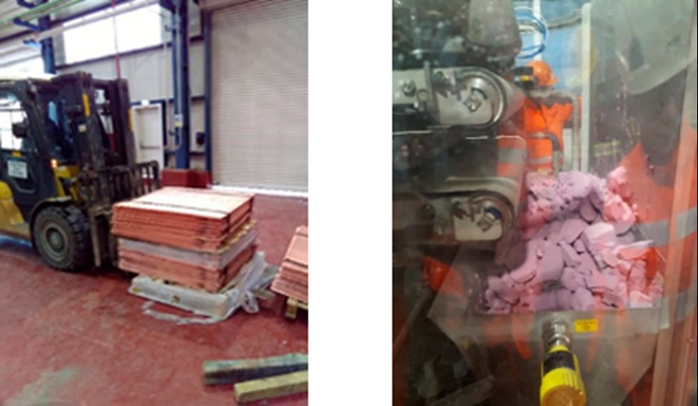
Figure 4 (left). Copper cathodes. Figure 5 (right). Cobalt carbonate
Two major lessons were learned. Firstly, it is important to ensure there are enough experienced personnel working on the commissioning phase. With that and good customer communication it is possible to create a quite rapid learning curve for the customer’s operating personnel. The second major lesson learned is the importance of selecting the right construction materials. This is vital when we are talking about high-pressure, acidic conditions.
Of course, commissioning is always about continuous learning and improving, both for Outotec professionals on-site and those in the office support organization. This site is a great showcase of our hydrometallurgical capabilities as it showcases all of the hydrometallurgical processes and equipment that Outotec has in its portfolio. The site is a reference for new customers and also serves as a training location for new Outotec engineers. And we were able to commission the plant in a relatively short time and stabilize the process to produce the correct amount of end product with the required quality. Thank you to all the colleagues who were involved in the different stages of this project.