The updated version of FeedGuard includes speed sensors, which are capable of measuring the speed of the material and thus the mass flow inside the AirSlide. The feed inlet from AirSlide to concentrate burner can get blocked when foreign material, such as pieces of sacks or dust lumps, is mixed into the concentrate feed. The feed inlet box is divided to four equal sectors, with two adjustable dividing plates, which distribute the concentrate or matte evenly to the concentrate or matte burner. This is assuming that there is no disturbance for this split, the inlet sections have been properly tuned and that the air slide and inlet has been correctly aligned. The FeedGuard provides the measurement and adjusting tool to ensure this.
Apr 17, 2018
Outotec® FeedGuard – ensuring optimal feed distribution online
Outotec® FeedGuard is based on the electrical capacitance tomography (ECT), capable of detecting even the smallest variations in the feed. The FeedGuard sensor is integrated to the concentrate or matte burner feed inlet port and provides the results of measurements to the control room online. The Outotec® FeedGuard provides means for easy and quick detection of uneven feed or feed blockages. It has low maintenance requirements (non-intrusive sensors) and it is based on a very accurate and reliable ECT measurement. An online measurement of feed distribution and ensuring that it is even and without blockages improves the oxygen efficiency of the process, decreases weak acid production and reduces the slag losses of Cu or Ni.
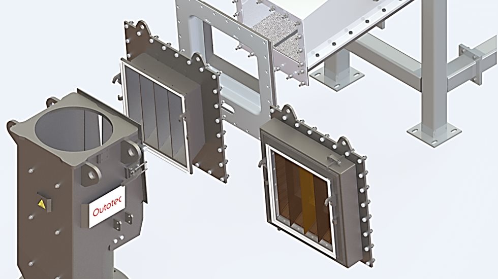
Figure 1: FeedGuard mechanical setup.
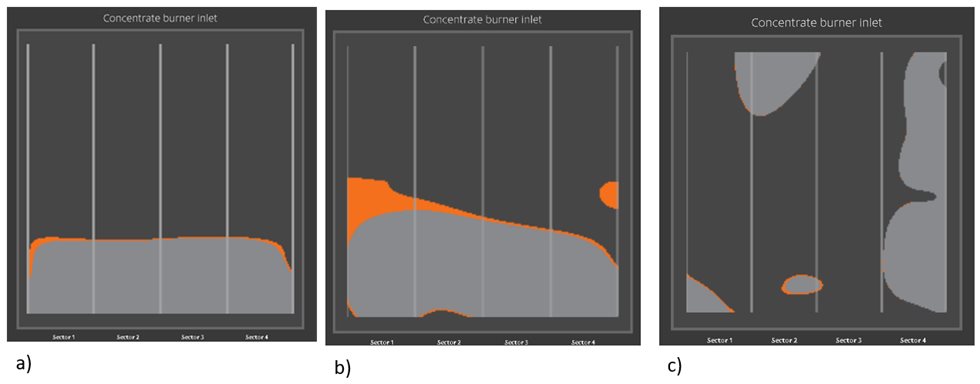
Figure 2. Tomographic imaging of the 4 sectors of feed inlet a) Normal distribution flow b) Tilted or interfered flow c) Severe blockage
One of the new features include the blockage index, which is automatically calculated by the FeedGuard using the speed sensors and signal delay variations. This enables to get more relevant information of the feed disturbances independently from mass flow variations caused by e.g. feed rate changes. With blockage index alarms the furnace operators could detect and predict blockages inside the AirSlide and fix them when needed.
The first FeedGuard reference has shown that the blockage usually starts from the two center sectors on the feed inlet and spreads towards the side walls. Once the blockage has formed, it should be removed as soon as possible. Although, occasionally the blockage goes away without interfering.
The new FeedGuard speed measurement data from a copper smelter was examined for a two-week period in December (Dec 4 – 17, 2017). The total amounts of blockages and durations are listed in Table 1.
Table 1. Blockage data from a two-week test period
Suppose that the number of blockages remain same as in the test period but the average reaction time reduces to only 15 minutes, the total blockage time could be reduced to about 4 hours per week. With 330 days of normal operation in a year the amount of blocked feed would decrease from roughly 25 % to 2.5 %.
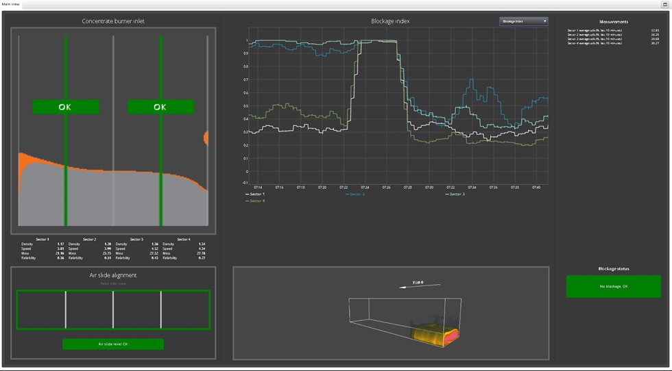
Figure 3. Basic view for the operators from the FeedGuard user interface showing the blockage index trend. At the moment inlet adjusting plate is good and the air slide alignment is good. The blockage index showed that earlier sections 2 and 3 were blocked and normalized after cleaning.
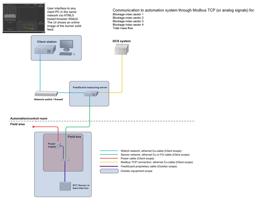
Figure 4. FeedGuard automation setup.
The mass flow indication was also compared vs. the feed rates of the individual feeds (concentrate mixture, dust and fine reverts). This period showed that the total mass flow of FeedGuard was very close to the total mass flow of the individual feeds, normally within 1 % error calculated over a fill cycle of the loss-in-weight feeder. Additionally, it was noticed that an underfeed in the material was not so much evened out by the air slide, whereas an overfeed in material was evened out much better in the air slide as shown in the picture below.
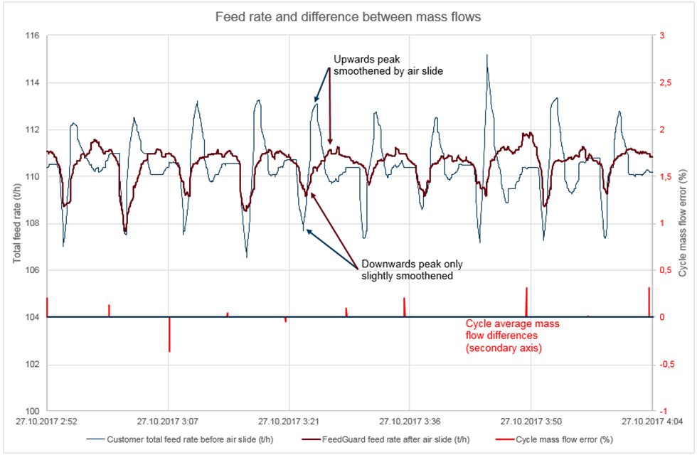
Figure 5. Total mass flow from individual feeders vs. FeedGuard mass flow.
The FeedGuard mass flow indication can be used to tune the feeder parameters in order to achieve a stable feed, for example if Loss-In-Weight feeders are used. The FeedGuard can be used to tune the parameters during filling and waiting time in order to achieve a continuously stable mass flow. The FeedGuard includes the following main features:
- Sector mass flow
- Total mass flow (feed rate)
- Blockage index, which can be sent as an alarm signal to the automation system indicating when the blockage has to be removed
- Live feed inlet tomography cross section in the user interface
- Live 3D image of the feed flow in the user interface
- Online alignment and adjustment visual guide in the user interface
The benefits of FeedGuard are:
- Spotting disturbances/blockages during feeding
- Spotting if AirSlide is tilted or aligned poorly
- Reducing non-uniform feeding and combustion in the concentrate/matte burner
- Alarms in automation system for blockage indication of each sector.
- Monitoring if feeding system works properly and allowing their tuning during volumetric cycles (fill or wait periods).