Metso Insights Blog Mining and metals blog When washing is not a good thing
Mining
Jun 13, 2017

When washing is not a good thing

Washout refers to phenomenon whereby repeated slurry movement gradually wears structural components of the rotating body of a grinding mill. This can occur for a number of reasons including liner neglect, backing rubber bond failure and incorrect liner design.

A Case Study of Outotec Rapid Response and Repair Minimizing Lost Production

Washout refers to phenomenon whereby repeated slurry movement gradually wears structural components of the rotating body of a grinding mill. This can occur for a number of reasons including liner neglect, backing rubber bond failure and incorrect liner design. On 18 September 2016 a slurry washout was detected on an Outotec grate discharge shell supported secondary pebble mill. The washout had occurred on the shell outside the pulp lifters adjacent to the discharge head plate. The damage was initially assessed as very serious; the material lost was approximately 3.7 m long and more than 70% of the shell thickness at some points.

Initial visual inspection of the affected area suggested no cracking of the mill shell in the washed out areas, however no specialist crack detection had been completed. Outotec were contacted to help the mill operator decide whether to:

Continue operating "as is" until a new shell could be sourced

OR

Perform a repair that could either; avoid the need for a new shell or allow secure operation of the mill until a new shell could be sourced.

Complicating the assessment was that in 2004 this same mill had a washout incident that was repaired and the condition of that repair was not well understood.

{{zoomedImageIndex + 1}}/4
{{ captions[zoomedImageIndex] }}

CIRCUIT/MILL DESCRIPTION

The circuit has an autogenous primary mill with a trommel screen to screen out 6-30 mm ore-pebbles. The ore pebbles produced are then used in the grate discharge secondary pebble mill as grinding media. The pebble mill operates in closed circuit with hydro cyclones, with a circulating load of about 140% of total feed. The mill design power draw is 4000 to 4400 kW, with 4500 kW installed power. Design charge level is 30-40 vol-%. The operational aim is to keep power draw close to 4400 kW for higher throughput. Mill operating pulp density is typically about 72% (w/w), feed SG is about 4.9 and pebbles are typically slightly lighter with SG about 4.7.

In this pebble mill the charge level often exceeds the designed 40 vol-% because of low the slightly lower SG of pebbles, high production rate and high circulating load. Typically the charge level is measured at 43 vol-% and there are rare known occasions when the mill charge has been above 50 vol-%.

FIRST ACTIONS

Operations wished to fill the affected areas with some liquid metal and monitor every month until a new shell could be delivered.

Outotec were very concerned that cracks could be present despite not being visually observed and that without extensive remedial work continued operation would result in catastrophic failure.

Due to language challenges Outotec provided a highly visual illustration of a repair process to be considered should cracks be present, see Figure 5.

Weld repair suggestion
Figure 5. Initial suggestion for Weld Repair.

In an effort to reduce downtime Outotec took the following actions in parallel.

  1. The mill operator was asked to properly clean out and sand blast the washed out regions of the shell and then complete Non-Destructive Testing (NDT) including magnetic particle inspection and ultrasonic testing.
  2. A Finite Element Analysis was started to assess the Principal Stress Difference (PSD), or stress range, in the mill when actual washed out geometries were included in the assessment.  The FEA was performed using Outotec’s in house Advanced Analysis Software. The FEA geometry scenarios were:
    a) As Original - the as supplied geometry
    b) Washout per Position 1 – this being a fairly typical wash out shape
    c) Washout per Position 2 - the point with the most severe washout damage
  3. A welding crew qualified in Outotec’s heavy plate weld repair procedure was put on standby to send to site in the event a weld repair was required.

RESULTS OF FEA

The FEA results reported high stress levels at 4 key locations:

Point 1- the Tee weld outside of the shell
Point 2- the Tee weld outside of the shell or the immediate area worn away by washout
Point 3- the stress in the washout at the thinnest point
Point 4- the stress seen on the outside of the journal

The loading used in the FEA was based on the "typical" operating duty of 43 vol-%. The results of the FEA can be summarised as follows:

The "as supplied" Original geometry was found to result in stresses compliant with Outotec specifications.
The Washout per Position 1 was found to result in Points 2 and 3 being greatly overstressed.
The Washout per Position 2 was found to result in Points 2 and 3 being greatly overstressed.

The illustrated FEA results are provided in Figure 6.

Results of FEA
Figure 6. Results of FEA, Geometry Scenarios with original geometry and worst-case washout.

RESULTS OF NON-DESTRUCTIVE TESTING (NDT)

The washout area was inspected using penetrative magnetic dye. As shown in Figure 7 the NDT found surface cracks, 24 in number were identified.

Based on the very stress levels predicted by the FEA at Points 2 and 3 it was assessed the cracks found in the washed out locations would grow extremely rapidly, therefore putting the mill back into service 'as is' was not recommended.

Surface cracks
Figure 7. First Feedback from NDT, 24 surface cracks.

Based on the very stress levels predicted by the FEA at Points 2 and 3 it was assessed the cracks found in the washed out locations would grow extremely rapidly, therefore putting the mill back into service 'as is' was not recommended.

NEXT STEPS & REPAIR PROCESS

Based on the findings of the NDT the mill operator was not confident the mill could ever be returned to a state suitable for long term operation. Therefore the focus was shifted to finding a way forward that would have the mill returned to service as quickly as possible whilst being suitable for continuous operation until a spare shell was available onsite. Accordingly in collaboration between the mill operator and Outotec the next steps and repair process were as follows:

Extend the FEA to include the geometry scenario:
a) Weld-repaired to 30mm - this is a partial weld repair scenario where the washout depth in all positions would be reduced to 30mm.
Mobilise the Outotec weld repair crew with their equipment and when mobilised employ Outotec's Heavy Plate Weld Repair Procedure to:
a) Remove the cracks
b) Perform the weld repair
c) Conduct NDT
d) Specify necessary remedial work until the acceptance criteria is met
Source high deposition welding consumables for two scenarios:
a) 30 mm partial repair: ca. 167 kg
b) Full repair: ca. 406 kg
Plan for the mobilisation of a journal linishing crew to ensure the needed bearing journal tolerance could be restored if the welding repairs caused distortion outside the acceptable criteria.

EXTENDED FEA RESULTS

While the repair crew was being mobilised the 4th Geometry Scenario "d." was completed. It was found that repairing the wash out positions so that not more than 30mm of material was missing compared to the original design would result in high stress Point 2 being over stressed, but not excessively so considering the Changed Objectives, while high stress Points 1, 3 and 4 were compliant to Outotec specifications, see Figure 8.

 Result of FEA
Figure 8. Result of FEA, Geometry Scenario d).

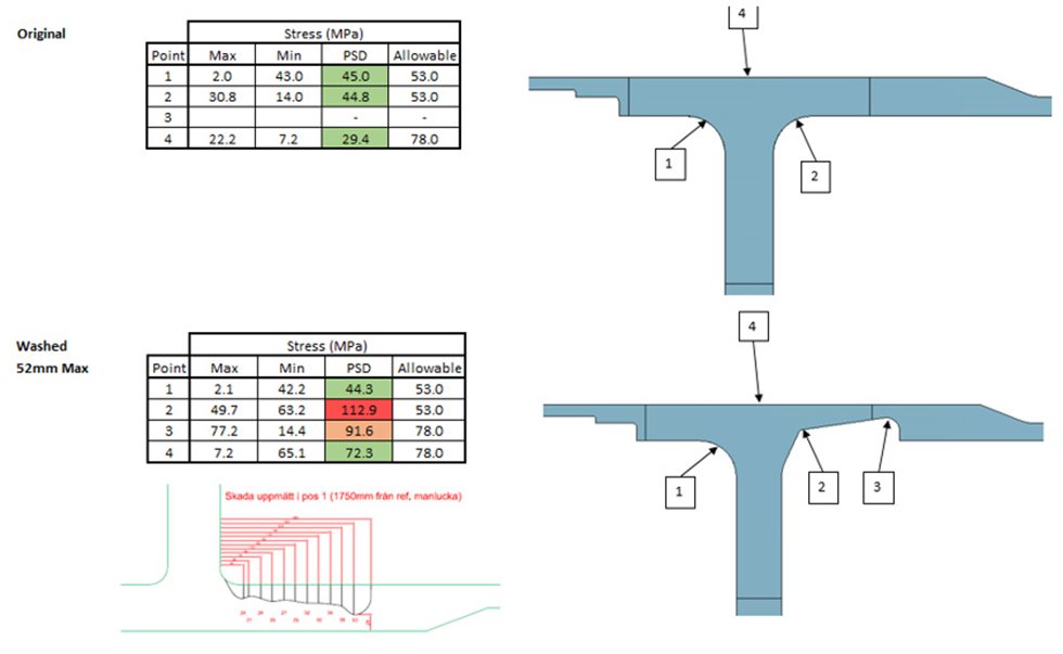
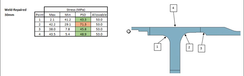
It was considered likely that the repair to 30mm would survive the 26 weeks of operation needed to achieve a new shell onsite. Accordingly through a consultation process between Outotec and the mill operator it was decided to repair according to this modified "less 30mm" geometry.

CRACK REMOVAL & WELD REPAIRS

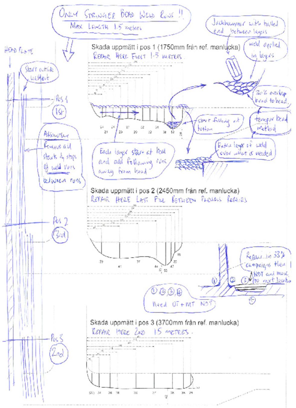
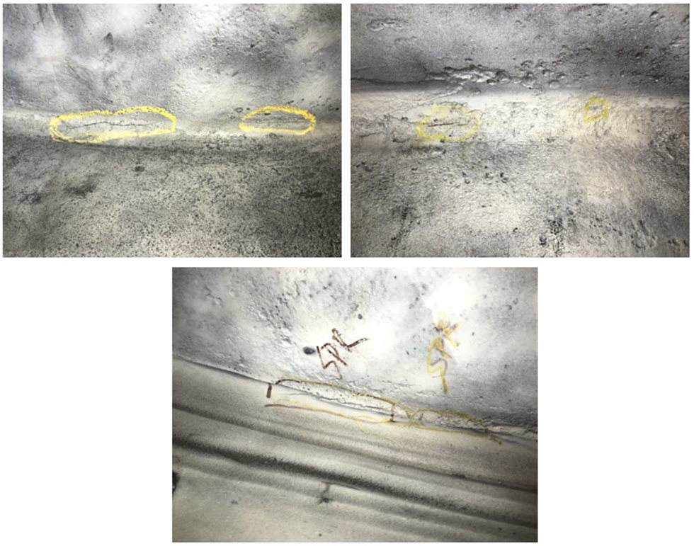
Outotec has a proven heavy plate weld repair procedure which has been employed successfully to repair numerous large wash out situations. The procedure is extremely onerous as the quality of the repair must be as good or better than a workshop performed repair; the procedure describes how:

The working environment is very challenging so must be environmentally controlled;
A lot of distortion can occur and time lost by poor crack removal techniques and what approaches must be employed to optimise the crack removal process;
Prequalified, high build rate, welding procedures can be used to speed up the repair process;
The component will not be thermally stress relieved after repair so what must be done to ensure the component does not contain excessive residual stresses post repair;
Cracking during welding is a high risk so what measures must be employed to avoid weld related cracking;
The component has been machined to design sizes and tolerances previously so how the repairs must be performed to avoid distortion that would render the component unserviceable;
Quality control must be employed to ensure the finished product is as intended.
From the time crack removal was started to the time when the weld repair passed quality control was circa 7 days. This timing, considering approximately 167 kg of weld consumable was deposited, was quite an achievement.

LINISHING OF BEARING JOURNAL

The secondary pebble mill floats on hydrostatic multi-pad shoe bearings utilising a lubricant film thickness of approximately 120 microns. While this is quite a deep lubrication film, the form tolerance for the bearing journal is quite tight. Although very little distortion occurred during the weld repair process it was decided to linish the discharge end bearing journal to ensure the form tolerance for the bearings was met. A third party specialist journal linishing company was contracted to perform the linishing process using a belt sander mounted on a machine bed with cross travel. On completion of linishing the bearing circuit was flushed to remove any traces of iron filings generated by the linishing process.

FINAL RESULTS

On Oct 19, 2016, one calendar month and one day after the wash out was first observed the mill was returned to full power operation while a replacement shell is being expedited.

The event caused a substantial challenge for the mill operator, however the situation brought about a scenario where Outotec and the mill operator worked together to expedite a solution with shared understanding of risk to the problem at hand. In this case there was an excellent outcome provided in a time that would have been unachievable had the collaboration between the mill operator and Outotec not occurred.

Mining