Metso Insights Blog Mining and metals blog Technical improvements of Tamano flash smelting furnace operation
Mining Metals refining
Jul 4, 2017

Technical improvements of Tamano flash smelting furnace operation

The Tamano Smelter & Refinery was originally designed for copper production of 84,000 mtpy. It now has a capacity of 260,000 mtpy, which was achieved in a stepwise manner through projects carried out over several years. An increase in oxygen enrichment, modifications to the furnace and feed system, and various other operational improvements have been carried out. The flash smelting furnace feed rate has been increased six times since startup. However, a higher matte grade has resulted in higher copper loss. In this paper, we describe the improvements made to the platform of the concentrate burner and the ceiling of the reaction shaft, and also the change made to the structural material of the uptake shaft plate cooling elements, which is now composed of bricks. Figure 1 shows the general view of Tamano Smelter.
View of Tamano Smelter
Figure 1: General view of Tamano Smelter

MODIFICATION OF THE TAMANO FLASH SMELTING FURNACE (FSF)CONCENTRATE BURNER

Previously, the Tamano FSF concentrate burner faced the following problems.

  1. The burner inspection hole layout did not allow for the cleaning and removal of buildup, which made inspections difficult.
  2. Thorough removal of the buildup was not easy for reason (1.) above, and we were forced to continue operation with a poor concentrate reaction.
  3. The thermal deformation of the platform structure in the concentrate burner area meant that the burner nozzle was prone to misalignment.
  4. The misalignment explained in (3.) helped the buildup to grow on the concentrate burner jacket and this led to an uneven concentrate reaction.
  5. Maintaining the proper function of the burner’s eccentricity detector and position adjuster was not easy, and the position adjustment was a time-consuming task.

We therefore made modifications such as changing the inspection hole layout. The layout was changed to a design that allowed the thorough and quick removal of buildup. In addition, we modified and replaced the supporting structure and also replaced the adjustment system consisting of a jack and a position adjustment device with a system fixed onto a welded plate to maintain the adjusted clearance for an extended period of time.

PEFORMANCE OF THE MODIFIED CONCENTRATE BURNER

The modification reduced the inspection frequency from an average of 3.1 times/day to 2.5 times/day, thereby lowering the operating load. The time required on inspections to reduce the rate of the concentrate charge by 15% was shortened by 55 hours/year and the dust generation rate decreased from 8.1% to 5.8%. The modification thus contributed to the stabilization of the reaction in the concentrate burner.

MODIFICATION OF THE TAMANO FSF UPTAKE SHAFT

Previously, the Tamano uptake shaft faced the following problems.

  1. Accretions grew on the uptake shaft’s inner surface because of the plate cooling element of the off-gas from the FSF, and required removal by scraping into the settler.
  2. The concentrate feed rate had to be reduced by approximately 30% (for approximately 4 hours at a frequency of once a week) during the abovementioned removal, and this operation represented a loss of productivity.
  3. The replacement of the plate cooling element was required at maintenance shutdowns (every 2 years), which meant that the repair cost was considerable.
  4. The abovementioned factor (iii) did not allow a longer shutdown interval.

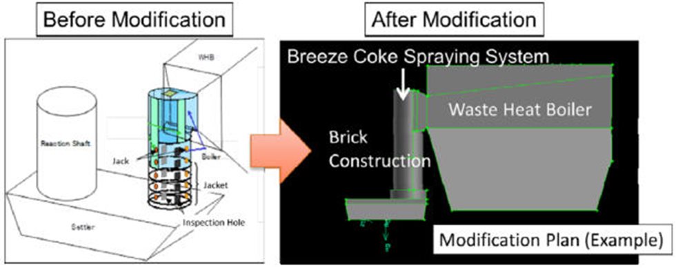
To solve the abovementioned problems, we changed the uptake shaft construction from a cylindrical plate cooling element design and a boiler to a refractory construction (Fig. 2). We also added a breeze coke spraying system to the top of the uptake shaft to reduce (deoxidize) the accretions that had stuck to and grown on the uptake shaft wall through coke spraying.

Before and after modification of the uptake shaft construction
Figure 2: Before and after modification of the uptake shaft construction

EFFECT OF THE BRICK CONSTRUCTION OF THE UPTAKE SHAFT

The previous uptake shaft construction faced problems that were eliminated by rebuilding the uptake shaft with bricks 2 years ago, as described below.

  1. The workload for operators involved in accretion removal reduced from 4 hours once a week to zero.
  2. The requirement for the abovementioned accretion removal operation, which lowered the concentrate feed rate for the FSF by approximately 30%, was reduced.
  3. There was a substantial reduction in the cost of major uptake shaft repair including the replacement of the plate cooling element.
  4. There was an elimination of long production stoppages due to water leaks in the plate cooling element.

The concentrate feed rate thereby increased by approximately 100 mt/day (the sum of approximately 60 mt/day due to the concentrate burner improvement and approximately 40 mt/day due to the uptake shaft modification). However, the brick construction of the uptake shaft resulted in an increase in the temperature of the gas flowing through the waste heat boiler by approximately 50 °C, which negatively affected the downstream process.

Conclusion

We changed the inspection hole layout and clearance adjustment method in the concentrate burner.

  • Dust generation rate improved by 2.3%
  • Concentrate feed rate increased by 40 tons/day

We changed the FSF uptake shaft design from a plate cooling element type to a brick construction.

  • A lower workload for the operators was achieved
  • Concentrate feed rate increased by 60 tons/day
Mining Metals refining