Metso Insights Blog Mining and metals blog Inching drives – one way to improve mill safety
Mining
Apr 11, 2022

Inching drives – one way to improve mill safety

Moris Fresko
Moris Fresko
Technical Support Director, Americas
Safety and sustainability are two important and strategic areas companies are striving to be better at in today’s business environment. Safety concerns the health and livelihood of employees working around all kinds of equipment. This blog discusses grinding mill inching drive safety in the operation of mines, and how minor and even fatal accidents can be avoided.

An inching drive, what is it and why is it needed?

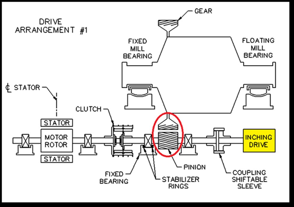
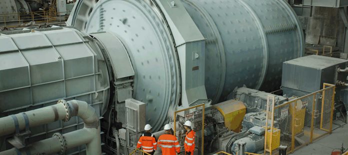
Grinding mills are typically designed for long life (minimum 20 to 25 years). It is not uncommon to see grinding mills still operating today with an age of 2-3 times their original intended lives. This is only possible with regular inspections and maintenance, which involves replacing normal wear items such as liners that protect the rotating structure, as well as replacing gears and pinions. Such inspections and maintenance require stopping the mill and turning the mill at very low speeds to the desired mill position. The main mill motors generally cannot be used for turning the mill at these low speeds. These motors may also not be available if they are being serviced at the same time. In such situations, we require auxiliary drives such as inching drives equipped with brakes so that the mill can be positioned and locked to allow personnel to safely enter the mill to perform their inspections or service work

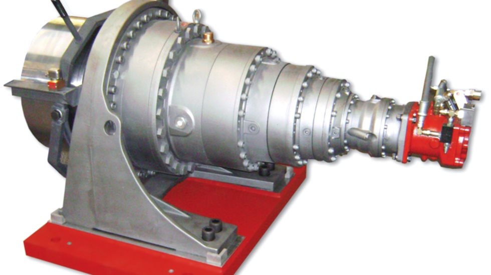
A large mill could be rotating at 10 to 15 RPM, depending on its size, during normal operation, yet an inching speed of about 1% of operating mill speed (i.e., 0.1 to 0.15 RPM) is sufficient to position the mill. Inching drives can be equipped with hydraulic or electro-mechanical motors.

A Hydraulic Inching Drive

Hydraulic and mechanical inching drives

Hydraulic inching drives typically consist of a hydraulic motor (hydraulic pump) which has multiple stages of planetary gears. They have their own lube units and are typically coupled to the mill pinion shaft. Hydraulic inching drives typically deliver high torques.

A hydraulic inching drive is connected to the mill through the pinion/gear.

Mechanical inching drives consist of an electrical motor coupled to its own gear reduction. Even though they can be designed to deliver higher torques comparable to hydraulic units, they are traditionally designed to deliver lower torques, and thus connected to higher speed items such as the main mill motor or the main mill reducer.

In the example above, a mechanical inching drive is connected to the mill through a gearbox reducer, then to pinion/gear.

Mill charge weight can be significant

Equipment such as Semi Autogenous Grinding (SAG) mills, ball mills, pebble mills and rod mills are some of the largest rotating equipment in mines that produce metals or industrial products such as cement. Mill charge typically consists of ore, steel balls (added to aid the grinding of the ore), and water (to lower noise and heat generation as well as to facilitate grinding and separation). A large 24-foot (7.3 m) diameter ball mill charge typically weighs around 2 million lbs (907 tons). Semi Autogenous Grinding (SAG) mill charge can be equally as heavy.

The charge starts tumbling at different angles, depending on the application and size of the mill. The charge cascade angle typically seems to vary but can go as high as 45 degrees from the horizontal.

Charge inside a SAG mill with steel liners.

If the mill were released from its maximum “non-zero energy state”, the mill can roll back and accelerate to speeds an order of magnitude larger than inching speeds (1 to 3 RPM). Hand calculations verify these numbers.

When charge load in the mill is centered, it is in “zero energy state”.
In the “non-zero energy state”, the charge develops a torque that wants to turn the mill.

Gear reduction needed to rotate the mill

Both hydraulic and mechanical inching drives require multiple stages of gear reduction to be able to rotate the mill. Consider the following example for a gear reduction.

A simple gear reduction.

In the example above with 3 gears which have a gear ratio of (30/18 teeth) x (18/10 teeth) = 3, the torque of the input gear would thus be a third of the torque required at the output gear, giving it a mechanical advantage to turn heavy equipment. This of course would come at the expense of reduced output speed. Ignoring mechanical losses in this drive train, the power transmission at each stage, defined as torque x speed, is constant.

The typical mechanical inching drive motor speed is around 1500 to 1800 RPM while the mill inching speed is in the order of 0.1 to 0.15 RPM. Thus, the gear reduction ratio between the inching drive motor and the mill is roughly 12,000 to 1. What this means is that the inching drive motor must turn 12,000 times to be able to turn the mill once. Consequently, if the inching drive brakes fail, then the mill’s unbalanced charge can spin the inching drive motor at speeds like 28,000 RPM. Similarly, if the inching drive accidentally stays engaged and the main mill motors are started due to faulty logic, then the inching drive motor will spin at speeds of 180,000 RPM - like a turbine - causing a catastrophic destruction of the inching drive. Accidents like this can be deadly, as we have seen inching drives explode into pieces in several cases.

The key to ensuring inching drive safety

It is important to point out that inching drives, as well as other drive train components, need to be maintained, serviced, and repaired per the manufacturers’ recommendations. Inch brakes must be regularly inspected and maintained in serviceable condition. Typical issues include worn through brake pad lining, worn disc/drum, incorrectly adjusted brake pressure (or not adjusted to compensate for pad wear), brake assembly not aligned to drum/disc, which can allow pads to drag, overheat and fail. A failure of the inching drive brakes can be deadly, which is why proper safety guards need to be in place. It is also good practice to always keep the mill areas clean and uncluttered.

When an inching drive is in use, the mill motor needs to be disabled, as it can drive the inching drive motor to destruction. This is why starting the mill motor when an inching drive is connected should be prevented. Similarly, when a mill is not being inched, the inching drive needs to be safely decoupled from the main drives. To prevent accidental starts, mills are typically equipped with so-called “Trapped Key Interlock” mechanisms.

A Trapped Key Interlock System

There is a key associated with the Trapped Key Interlock systems, which provide a mechanical means of locking and unlocking devices in a fool proof manner. The key can only be used to either start the mill motor or lock the inching drive coupling to the mill drive, but not both. When an inching drive is no longer used, it is retracted and locked in the disengaged position by the trapped key device, and only then can the key be removed to be used in the sister trapped-key device in the main motor panel (MCC) to unlock the main motor circuit breaker from the racked-out position. This then allows it to be racked in, which traps the key in the main motor trapped-key device. It is critical that the trapped-key interlock system is regularly inspected and fully functional to prevent catastrophic failure and potential serious injury, or even death.

Grinding the mill out (cutting the feed to the mill), thus reducing the charge load prior to mill maintenance is a good practice. This lowers the weight of the charge, thus the roll back torque. Also, after inching the mill to desired position, it is advisable to roll the mill back to its “zero-energy state”. This can be verified with cameras that look inside the mill, or by disengaging the inching drive with the hydrostatic oil supply on in the case of pad or slipper bearings.

Current best practice is to have additional engineering controls on top of the trapped key interlock, such as proxies monitoring the position of the inch coupling, armoured and fully encapsulating inch brake covers, plastic inch motor fan blades and an inching drive speed switch. Upgrading older mills which have just the trapped key interlock with some of these additional controls is highly recommended.

The latest and greatest development in inching drive safety is the safety rated Variable Speed Drive (VSD) system for the inch motor, which prevents uncontrolled mill rollback in the event of brake failure. This is a new product and is in the final stages of development.

In short, proper maintenance, fool-proof safety locks, mill logic and following well designed inching protocols are critical to ensuring the safe operation of mills.

WEBINAR
Have you inspected your grinding mill lately?
Enjoyed this article? Try this next
What you do not see can hurt your mill
Learn about the top three undetected issues in grinding mills and how to catch them.
Read more
Mining