Metso Insights Blog Mining and metals blog Grindforce - back to basics
Mining
Jun 19, 2017

Grindforce - back to basics with HIGmill fine grinding physics

Stirred milling and attrition type grinding has overtaken traditional tumbling mills and impact grinding to become the comminution benchmark for regrinding circuits in flotation plants and fine grinding in leaching operations, due largely to energy efficiency gains. This major shift towards stirred milling has predominately been driven by decreasing mineral particle liberation sizes of today’s mined ore deposits where finer grinding requires significantly more comminution power. In addition, ore head grades are decreasing, resulting in the need to crush and grind more rock to produce the same amount of valuable metal.
HIGmill

With the current drop in commodity prices, the mining industry requires innovative technologies and solutions that can reduce operating costs and a key area for improvement is energy savings. Outside the mining sector, there are technologies that can have valuable crossover applications. Of particular note are opportunities for technology and know-how crossover arising from the similarities between hard rock mining and industrial minerals industries. One such crossover technology from industrial minerals is the Outotec HIGmillTM, which was developed over many years with the primary design motivation being significant energy savings for the grinding of fine particles.

The following discusses the fundamentals of the stirred milling process and attrition type grinding, and why the unique HIGmill is fundamentally the most energy economical grinding mill of this type in the world today with the introduction of the latest GrindForceTM mechanism.

The Technology

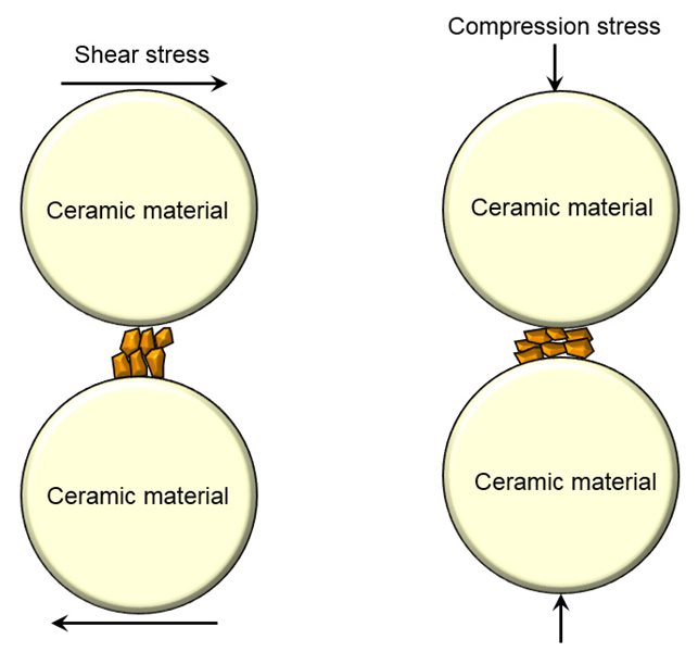
The HIGmill itself is a vertical, fine grinding, stirred mill comprising a drive train attached to a rotating shaft within a stationary grinding chamber shell. Attached to the shaft are GrindForce rotating grinding rotors, not flat discs like traditional stirred mills. These grinding rotors agitate and mix the bed of fine (2 to 6 mm) ceramic grinding media producing a highly efficient, attrition grinding environment. Attached to the shell are GrindForce counter stator rings, again unique to the HIGmill design. Feed slurry moves upwards and passes into the grinding zones between these stator rings and the wall lining.

Space around every rotational rotor can be regarded as a classification stage where coarser particles move towards the chamber walls while finer particles move faster upwards through the rotor openings. Due to the vertical arrangement of the HIGmill, classification is conducted simultaneously throughout the grinding process with larger particles remaining longer at the peripheral where there is a high concentration of media particles, while smaller particles move upwards. The stator rings create separate grinding zones around each rotor, and the HIGmill has between 15 and 20 of these zones, more than any other stirred mill on the market. In addition, these distinct stator rings force slurry and media to each grinding zone, eliminating any possibility of particle short-circuit or dead zones within the grinding volume of media which occupies between 60-70% of the total mill volume.

Physics

Ideas in physics can explain fundamental mechanisms of stirred milling, in particular the HIGmill which was developed over many years with the design motivation of power savings. This article goes back to the basics of physics to explain rudimentary principles of operation of the HIGmill and why the unique tubular vessel design with grinding rotors and stator rings operating in plug-type flow is ideally suited for efficient, stirred mill grinding of mineral particles in slurry streams.

Plug Flow

An appreciation of fluid mechanics plug flow theory, where there is essentially no back mixing with "plugs" of fluid passing through a tubular vessel, is helpful in understanding the important benefits of the HIGmill design.  In fluid mechanics, plug flow is a simple model of the velocity profile of a fluid flowing in a pipe, where the velocity of the fluid is assumed to be constant across any cross-section of the mixing chamber perpendicular to the axis of the flow through the chamber.  The fluid flow and mixing patterns occurring within the HIGmill grinding chamber can be considered analogous to a chemical engineering plug flow or tubular reactor.  A tubular reactor is a simple continuous reactor where pumps deliver the reactants through the base of the vertical vessel, not unlike the slurry pumps which deliver material to the HIGmill.

Chemical engineering reactors do not meet ideal conditions of flow and mixing if the liquid dispersion deviates from ideal plug flow conditions and short-circuiting and dead spaces exist within the reactor chamber.  Therefore, creating a stirred grinding mill, like the HIGmill, with the basis of a plug flow reactor, can eliminate mineral particle short-circuiting and dead zones within the grinding chamber volume.  Further the plug flow design reduces unwanted back-mixing of particles, resulting in a more uniform final ground product with a steep product size distribution having as many particles as possible close to the target grind size (P80) as possible.  A steep size distribution is very important in optimization of the downstream flotation or leaching process that follows a fine grinding unit operation, allowing optimization of metallurgical recoveries and grades.

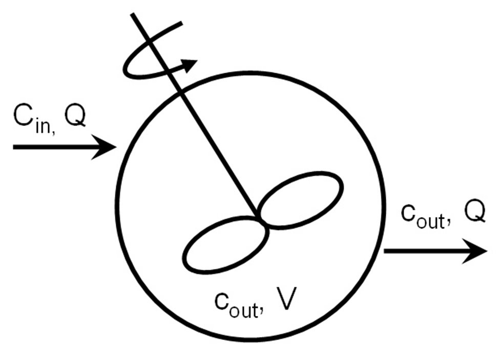
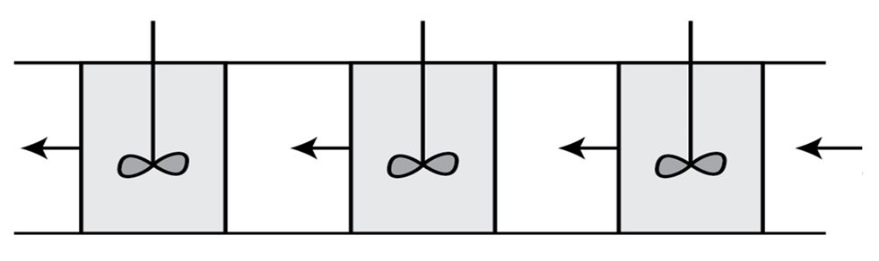
In theory to create perfect plug flow, an infinite number of continuous stirred tank reactors (CSTRs) are operated in series.  A single CSTR assumes that the concentration of the inlet fluid is instantaneously mixed and is equal to the outgoing concentration exiting the single vessel (Cin = Cout).  This is depicted in the Figure 1.

A single CSTR
Figure 1: A single CSTR assumes that the concentration of the inlet fluid is instantaneously mixed and is equal to the outgoing concentration exiting the single vessel

On the other hand, in chemical engineering practice, multiple CSTRs are operated in series so that plug flow conditions can be approached as indicated in Figure 2. The individual grinding zones between the HIGmill GrindForce stator rings act just like a series of CSTRs, where the 15-20 zones in the tubular HIGmill vessel allows the mixing to approach theoretical plug flow. Essential components for plug flow are a continuous flow and a tubular vessel design, both key elements in the HIGmill design. The HIGmill design is a vertical tubular grinding chamber with the largest aspect ratio of all stirred mills on the market today.

Multiple CSTRs
Figure 2: In chemical engineering practice, multiple CSTRs are operated in series so that plug flow conditions can be approached.

Attrition Grinding

From a particulate technology point of view, the product quality and grindability in a HIGmill is determined by three main factors, namely; 1. shear and compression stress mechanisms generated by the grinding media; 2. frequency a feed particle is stressed; 3. intensity of each stress event.

The particle grinding mechanism in stirred milling is almost 100% attrition or shear type grinding, , rather than impact grinding as occurs in tumbling mills, like SAG and ball mills.  Large particles (> 1 mm) can be efficiently reduced in size by impact grinding where the breakage method is shattering of particles by direct fall upon them from crushing bodies, like steel balls in a tumbling mill.  However, when fine grinding (< 1 mm particles) is required by the metalliferrous process, attrition or shear grinding is more efficient, especially when the grinding machine is required to produce particles less than around 75 µm.

There are two major types of grinding mechanisms in attrition type stirred, milling machines, namely; 1. shear stress between two surfaces, which is stress parallel to a surface of material, like grinding media or mill wall).; 2. compression between two surfaces, which is stress perpendicular to a surface of material.  These mechanisms are illustrated in Figure 3.

types of grinding mechanisms
Figure 3: There are two major types of grinding mechanisms in attrition type stirred, milling machines.

The frequency a feed particle is stressed by the above mechanisms is proportional to the number of particle-media contacts and the probability a particle is captured and sufficiently stressed, which are both very dependent upon the actual fine grinding machine design. The specific agitator design, number of grinding zones within the chamber, agitator speed, residence time and the presence or absence of particle short-circuiting and dead zones are all critical machine characteristics that the HIGmill addresses with the latest GrindForce design. Further the HIGmill is the only stirred mill on the market utilizing the unique GrindForce stator rings attached to the shell walls effectively eliminating the possibility of particle short-circuiting through the mill, while the tubular design with more grinding zones than any other mill excludes any potential dead zones within the vessel.

Grindforce

GrindForce is the trade name for Outotec's new profiled grinding rotor for use in stirred milling, taking its name from the very successful FloatForce® technology, which like GrindForce, is a new-generation mixing mechanism. The key to the new HIGmill design is the agitator (grinding rotors) and grinding chamber stator rings themselves, just like the rotor and stator in a mechanical flotation cell. The heart of the flotation cell is this rotor-stator mixing mechanism, which mixes the slurry, disperses air and generates kinetic turbulent energy. Turbulence is needed in order to accelerate the particles and give them sufficient energy, so that good particle-bubble contact occurs. Similarly in a HIGmill, the GrindForce mechanism more efficiently agitates the ceramic grinding media for improved particle-media interaction.

The agitator of the first HIGmill installed in a metalliferous operation included a number of changes to material of construction compared to the rotors used in white minerals processing, yet the fundamental design and profile were more or less unchanged.  The basic design was a flat one-piece disc with angle spoke arrangement, keyed to match the shaft, much the same as other stirred disc mills on the market today.  However, Outotec’s design engineers were striving to develop a totally unique technology to the current market norm and set about this task utilizing the internal comminution team’s world class, in-house DEM capability.  The DEM focused on the shear/spillage between a flat surface of a grinding disc and the media bed, plus the amount of media agitation that can be achieved by a flat disc.

This result of this work was a move away from the normal flat surface grinding discs to profiled grinding rotors with counter stator rings, together making up the GrindForce mechanism.  The DEM showed with this new rotor design, the velocity of the grinding rotors and media bed in contact with the rotors would be roughly the same, dramatically reducing the shear/spillage which causes wear.  A further significant benefit the DEM indicated was improved media movement with the rotors compared to flat discs.  The DEM work indicated a flat grinding disc surface is not the ideal design for mixing, and the media mixing/agitation is what creates the attrition grinding in stirred mills by increasing the stress intensity and the frequency a feed particle is stressed by the media bed.

From the DEM modelling, full scale grinding rotors were produced and installed in a large metalliferrous concentrator and results monitored over an 8 month period.  The results were outstanding with our benchmark 4,000 operating hours between grinding rotor replacements being surpassed given only a third of the new GrindForce rotors required replacement after such time.  The added effect of the GrindForce vane rotors on the process performance was excellent with a significant improvement in grinding efficiency to the target grind size.  This is due to the improved power transfer between the GrindForce rotor surface and the media bead mass, compared to flat surface discs.  Figure 4 highlights the significant improvement in energy efficiency from a full scale HIGmill operation before and after the introduction of the latest GrindForce grinding rotors, especially considering at the time of this reported data, only 9 of the 17 original flat discs had been replaced with GrindForce rotors.

GrindForce* Grinding Rotors – Energy Efficiency Full Scale
Figure 4: GrindForce* Grinding Rotors – Energy Efficiency Full Scale.

*NOTE – Photos and diagrams of the GrindForce mechanism and grinding rotors have deliberately been omitted for protection reasons. However we encourage interested persons to contact Outotec directly to view images of GrindForce.

Summary

Outotec HIGmillsTM have guaranteed proven performance results and high grinding efficiency. An understanding of physics and internal research and development with stirred grinding mill hydrodynamics has resulted in the Outotec GrindForceTM rotor and stator design, which is launched a year after the HIGmill itself. Full-scale operations have proven that HIGmill performance, which is already industry leading, can be further improved along with important wear performance enhancements with the application of GrindForce rotors and stators. Now all Outotec HIGmill grinding mills are equipped with GrindForce technology which furthers the energy and wear performance gap between Outotec HIGmills and other stirred mill solutions.

Mining