In order to enable the continuous production of sulfuric acid, the gas must be thoroughly cleaned. All inorganic matter which could contaminate the acid, or impact the plant’s operation by decreasing plant availability, must be removed from the gas. This requires both the hot gas system and the wet gas cleaning system to be carefully designed. The design data for gas treatment systems usually fall within the ranges shown in Figure 1.
Sep 23, 2019
Gas cleaning plant designs for the smooth operation of metallurgical smelting facilities
Pyrometallurgical processes for the treatment of sulfide ores are operated at temperatures of 800-1,500°C. In a metallurgical furnace, the sulfur contained in the ore is released into the gas phase as sulfur dioxide (SO2), an acidic gas that can be harmful to humans, vegetation, and property if allowed to escape into the atmosphere. Thus, in most regions, SO2 must be removed before the off-gas is released.
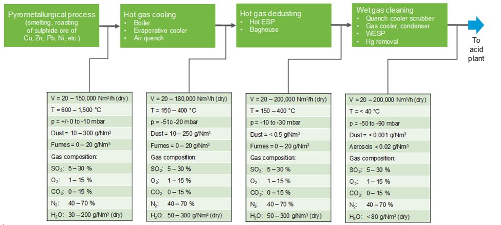
Figure 1: Design data for gas treatment systems
The design for a gas cleaning system must take the operation of upstream installations into account. Gas treatment systems for metallurgical furnaces releasing SO2-containing gases usually consist of gas cooling and hot gas dedusting systems, followed by a wet gas cleaning system.
A wet gas cleaning system typically comprises a quench cooler (quencher/scrubber) that converts the heat of the gas into water vapor, followed by a gas cooling or water-condensing system. The remaining dust and aerosols are then removed in wet electrostatic precipitators. Additional installations may also be needed to remove other substances, such as halides or mercury.
The task of the gas cleaning system is to ensure the reliable operation of the plant, producing sulphuric acid at a specified concentration (e.g. 98.5% concentration) and purity – acid contaminants including heavy metals such as arsenic, lead, antimony, selenium, and mercury must remain within permitted levels. Acid mist removal is also necessary to prevent corrosion within the acid plant itself, while fluoride removal protects the candle filters in the absorbers from damage; dust removal upstream of the plant must be used to avoid clogging of tower packing and mist eliminators.
The hot SO2 gas leaving the metallurgical process must be cooled before entering the dedusting system. Several technical solutions can be considered for hot gas cooling. In a waste heat boiler, the heat from the gas is recovered as saturated or super-heated steam. The boiler must be designed to operate reliably with acidic gases, and often sticky dust as well. For some applications, the effort required for energy recovery does not justify the use of a boiler. In these instances, horizontal spray chambers or vertical evaporative coolers are used instead. Fine water droplets, produced using high pressure or compressed air, are sprayed into the hot gas, with the water evaporating and adiabatically cooling the gas. The spray system must be carefully designed to ensure that the water evaporates while also eliminating the risk of wet dust build-up. If this is unavoidable, either a cold air quencher or gas coolers designed as goose-neck ducts can be used.
The hot gas cooling process is generally followed by a dedusting system. Simple systems, such as settling chambers and cyclones, use only mass-based forces such as gravity and centrifugal force to separate dust and gas. For more efficient dedusting, filters and electrostatic precipitators can be applied; using a filter for dedusting is the cheapest solution. Bag filters can only be utilized when the gas temperature can be safely maintained at below 200°C without risking acid dew point problems such as corrosion or build-up of sticky dust. Where dew point-related issues arise, dedusting must occur at higher temperatures, in which case a hot electrostatic precipitator designed to withstand peak temperatures is needed.
A serious problem that can affect hot electrostatic precipitators (HESPs) is dust build-up, which is often attributed to air ingress. Air entering the HESP, and in particular its water content, can result in a build-up of cement-like dust, which can short circuit HESP and necessitate mechanical cleaning. The “elephant legs” in the upper part of the discharge electrodes are an example of this type of dust build-up.
Wet gas cleaning systems
A wet gas cleaning system for a metallurgical sulfuric acid plant consists of a series of units (see Figure. 2).
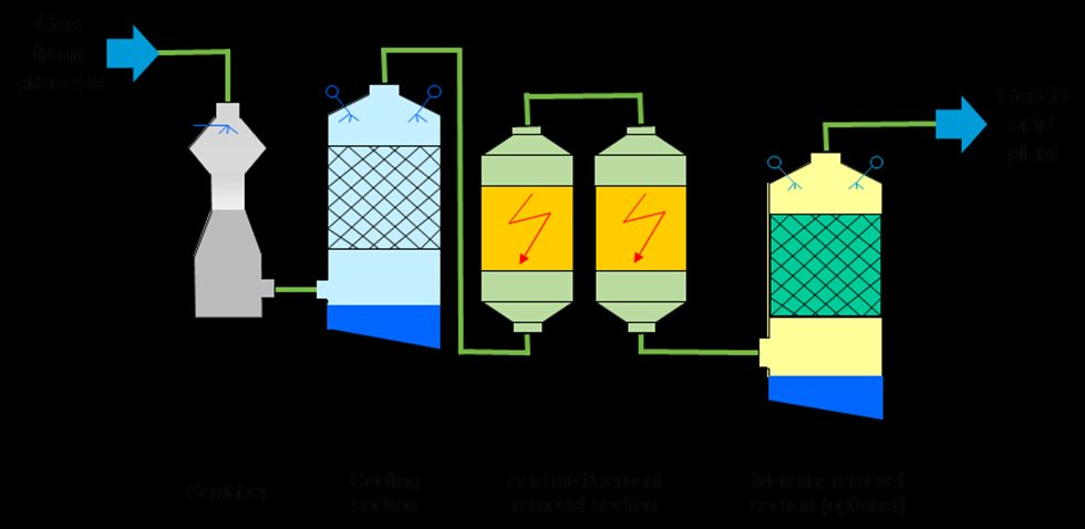
Figure 2: Wet gas cleaning system
These units are as follows:
• Quench cooler: This unit is always installed. Depending on the plant’s requirements, the quencher can also be designed for scrubbing or dust elimination. At the quencher outlet, the gas is fully saturated with water.
• Scrubber: A scrubber is designed to remove dust from the gas flow; the liquid injected into the scrubber captures the dust particles. Scrubbing efficiency can be improved by increasing energy input into the system. Scrubbers may have different designs depending on the required dust removal efficiency, gas flow characteristics, and dust type.
• Gas cooler, water vapor condenser: In this unit the gas is reduced to the maximum amount allowed according to the sulfuric acid plant’s water balance. The amount of water vapor allowed depends on the SO2 content of the gas. When the gas is cooled, the water vapor is condensed.
• Two-stage wet ESPs (WESPs): Fine dust particles and aerosols are removed from the gas in wet electrostatic precipitators.
• Subsequent stages: Elements or compounds that cannot be sufficiently removed from the gas by the above-mentioned units are treated in additional stages. This is the case for both gaseous metallic mercury and halides.
Quench coolers and scrubbers
Many technical solutions have been developed for quenchers and scrubbers. In the quencher, independent of the apparatus design, the gas is cooled when the water evaporates. The heat from incoming gas with temperatures exceeding 300°C is used to evaporate water, which is then sprayed into the quencher. The sensitive heat of the gas is converted into water vapor (latent heat). The energy (enthalpy) from the incoming gas flow (with a high temperature and low water vapor content) is the same as the enthalpy from the outgoing gas flow (low temperature and highwater vapor content). This type of cooling can be considered an adiabatic process, i.e. a process operated without any energy exchange with the external environment. The gas is usually saturated with water at the outlet of the quencher (or scrubber). If the temperature is lowered, the water vapor will condense.
The quencher normally has a temperature and acid-resistant brick lining. If the downstream installations are sensitive to temperatures exceeding 80°C, the quencher needs to be equipped with two fully independent liquid circuits. Each circuit must have its own pump, pipes, and nozzles. This 100% redundancy ensures safe operation in the event of a pump or nozzle failure. In addition, Outotec recommends installing an emergency spray system that will automatically activate in case of a power failure caused by excessive temperature.
A quencher can also be designed with high dust removal efficiency; in cases where substances condensed in the quench cooler need to be removed from the gas, a separate scrubber downstream of the quencher (humidification tower) is recommended. This is the case for arsenic released from copper smelters, for example. Scrubber and quencher design and selection will depend on process requirements such as gas flow rate, dust load, presence of condensable matter in the gas, required efficiency, dust type, and particle size distribution, as well as the amount of solids and dissolved matter in the scrubbing liquid.
An important feature for scrubbers is careful nozzle selection. Nozzles should be designed to withstand possible temperature excess and also abrasion resulting from particles suspended in the scrubbing liquid. Some scrubbers have special design features for handling fluctuating gas flow rates; this is the case in scrubbers with an adjustable throat. An adjustment can be made to the cross-section area of the scrubbing zone. This adjustment affects pressure drop, and as a result, scrubbing efficiency. During operating conditions which require a lower level of scrubbing efficiency, the pressure drop can be decreased to reduce energy consumption.
The most critical area in a quencher is the transition zone from hot and dry to wet and acidic. Both areas require different types of bricks and mortar. To ensure that there is a clearly defined transition zone, Outotec has developed the Otovent, a venturi-type quencher equipped with a ring zone, which allows for a clearly defined wet-dry transition zone (see Figure 3).
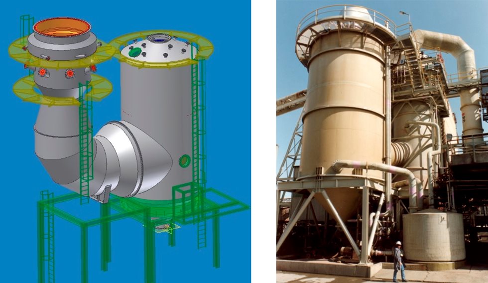
Figure 3: The Outotec Otovent venturi scrubber
Usually, any excess liquid from the wet gas cleaning system is discharged from the quencher circuit as weak acid, which is neutralized in an effluent treatment system. To reduce lime consumption, the SO2 dissolved in the weak acid is stripped out in a stripper, which is usually designed as a packed tower using ambient air. If a substantial amount of solid content is present, settlers are used to reduce this in the weak acid circulated in the quench cooler’s spray circuit.
Gas cooling / water vapor condensing systems
While passing through the quencher or scrubber, the SO2 gas is saturated with water vapor. In the acid plant’s drying tower, this water vapor is completely removed via absorption into the circulated sulfuric acid. When sulfuric acid is formed, the following equation applies:
SO2 + H2O + ½ O2 → H2SO4
In the SO2 gas there is one molecule of water vapor for each molecule of SO2. Design criteria for the gas cooling stage include the temperature at the inlet, based on the enthalpy of the incoming gas, as well as the gas SO2 content, and consequently water vapor content going to the acid plant – factoring in a certain safety margin. The inlet and outlet pressure must also be considered. The system must be designed to account for dust and aerosol load, as well as halides and dissolved matter in the cooling liquid.
Direct cooling of the gas in gas-to-liquid heat exchangers made of acid-resistant materials such as plastic and lead can reduce the gas temperature until it is very close to the cooling water temperature. However, these coolers, where the gas normally flows through the tubes and the cooling water is guided around the tube bundles, may also be subject to build-up, and because of their mechanical design they are very difficult to clean. The most popular gas cooler / condenser model is the packed gas cooling tower, where liquid cooled in plate heat exchangers is circulated over packing made of filling bodies. This “indirect” gas cooler / condenser can be designed to minimize build-up in both the packing and the cooling liquid circuit.
Wet electrostatic precipitators
Scrubber efficiency drops significantly for particles smaller than 5 µm. These particles are removed using wet electrostatic precipitators (WESPs). Aerosols and dust are eliminated from the gas using high tension. The gas flows through a strong electrostatic field, which is created by grounded collection electrodes and negatively charged / discharged electrodes, where an “electrical corona” is created. This corona releases electrons and electrically charged gas molecules, mainly oxygen. When these ions come into contact with aerosols and particles, they also pick up a charge. Guided by the electrostatic field, the negatively charged particles then migrate to the collection electrodes, where they are discharged and form a liquid film. The liquid film flows downward and drips into the bottom of the casing, where it is then drained.
Design parameters for WESPs are the actual gas flow and the efficiency required for dust and aerosol elimination. Operating temperature and pressure are needed for mechanical design, and the gas composition and trace gases also need to be determined. We recommend a two-stage system to ensure consistently reliable operation of this important component of the wet gas cleaning system.
Modern WESPs are designed with either round or hexagonal collection tubes, made of plastic and arranged in bundles. The discharge electrodes are mounted in the center of the tubes. Various materials can be used for WESPs: the casings are made of fiber-reinforced plastic (FRP) or coated steel, and the collection electrodes can be made of stainless steel or other corrosion-proof materials.
The illustration in Figure 4 shows a WESP based on an Outotec design (EDITUBE). The unit can be manufactured using stainless steel or plastic, and the gas flow is usually oriented downwards.
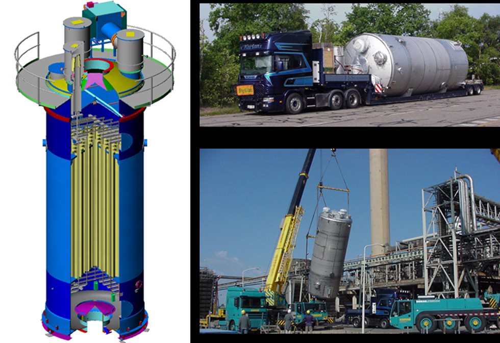
Figure 4: The Outotec EDITUBE WESP
The insulators that support the discharge electrode system are an important component of every WESP. Due to the moist, acidic environment inside the WESP, any condensation must be prevented from coming into contact with the insulators. There are two techniques that can be implemented to prevent condensation: electrical heating, and air flushing. Electrical heating is preferable in cases where the SO2 gas must not be diluted, whereas air flushing is a better solution if a WESP is operated under overpressure or fluctuating conditions.
WESPs are usually equipped with a flushing system for cleaning the internals (discharge and collection electrodes). Cleaning usually takes several minutes, and during this time the high tension is switched off. The decision over whether the vessel should be bypassed must be made based on the process design of the installation.
Mercury removal systems
In cases where a significant amount of metallic mercury is present in the gas, a separate mercury removal system is required. Although a large portion of the mercury is removed by reactions with other ions such as selenium and chlorides in the wet gas cleaning system, there may still be sufficient gaseous metallic mercury to contaminate the product acid. A number of different processes have been developed for the elimination of mercury, the most popular of which is the Boliden Norzink Process (calomel process), shown in Figure 5.
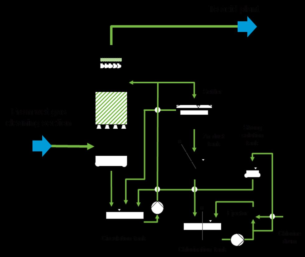
Figure 5: The Outotec Boliden Norzink mercury removal process
The principle of the Boliden Norzink process is that gaseous metallic mercury present in the SO2 gas reacts with mercury chloride dissolved in a reaction liquid, forming a solid mercury chloride compound known as calomel.
Hg + HgCl2 → Hg2Cl2
Where:
• Hg is gaseous;
• HgCl2 is in dissolved complex form; and
• Hg2Cl2 (calomel) precipitates as solids.
Calomel is removed from the reaction liquid circuit via liquid-solid separation in a settling tank and stored in a tank located beneath the settler. Prior to discharging the excess liquid, the dissolved mercury chloride is also precipitated by adding zinc dust. The reaction liquid containing the dissolved mercury chloride is prepared in batches by the chlorination of calomel with chlorine gas. This concentrated “strong solution” is then stored in a storage tank and added to the reaction circuit, where it is diluted to the concentration required for the operation of the system.
In addition to the standard process, a number of other methods have been developed in a variety of smelters to remove mercury from the SO2 gas or from the produced acid itself. Generally, all of these processes have been designed to achieve sulfuric acid with a mercury content of less than 1 ppm. If a mercury content of less than 0.1 ppm is needed, some copper smelters apply additional mercury removal stages, which have been designed as adsorption processes. These are usually arranged downstream of the calomel process. The mercury-containing SO2 gas passes through an absorber with several layers of an absorption agent, which reacts with the mercury to form an insoluble mercury compound. Selenium is one of the absorption agents that may be used for this. We offer a process that utilizes a scrubber stage with a selenium filter to achieve a mercury content of less than 0.1 ppm.
Halide removal systems
By this stage, a significant portion of halides has been removed in the scrubber and the packed gas cooling tower by absorption into the circulated liquid. If there are high liquid temperatures and high concentrations of absorbed matter present, substantial amounts of gaseous halides may still reach the acid plant, which can result in damage to the candle filters due to fluoride attack.
Sodium-silicate can be added to the liquid circulated in the packed gas cooling tower to reduce the concentration of dissolved fluorides. In the event of a very high halide content, a separate fluorine removal tower must be installed. Fluorine removal towers are designed as vessels equipped with ceramic filling bodies. The gas flows downwards, concurrent with liquid circulated in the tower. The filling bodies are eaten up by the fluorides and occasionally need to be replaced. To minimize the acid load and carry-over into the acid plant, the fluorine removal tower is often installed between the two stages of WESPs.
Gas cleaning system audits
If problems are observed in a scrubber, it is often useful to place the palm of one’s hand onto the individual pipes supplying the nozzles with liquid. A human palm is normally very sensitive to temperature, and if the temperature of one of the pipes is noticeably different, that nozzle may be lost or blocked. Nozzle loss can be considered more critical than the blockage of a pipe.
The trend of electrical values is a good indication of WESP operation. If the second stage is in operation with little flashover (maximum three to five flashovers per minute) and the specific electrical current exceeds 0.3 milliampere (mA) per square meter of collection area, the WESP can be considered to be functioning correctly; if this is not the case, we recommend a more detailed investigation to determine the cause of the deviation.
For other stages involved in gas cleaning systems, such as mercury removal or fluoride removal, we recommend regular sampling and analysis of the circulated liquid. A good estimate of the overall operation of a wet gas cleaning system with WESP is a lamp section (a 40-watt bulb with a sight glass, at a distance of five meters). If no clouds are visible, the sulfuric acid mist content is definitely below 25 mg/Nm3. By installing a simple instrument for measuring opacity, the mist content and the overall performance of the gas cleaning system can be viewed on the control monitor in the acid plant control room.
Last but not least, we recommend having an expert assess the system every 12–18 months.