Metso Insights Blog Mining and metals blog Diagnosis of wear patterns in centrifugal slurry pumps
Mining Metals refining
Jun 8, 2018

Diagnosis of wear patterns in centrifugal slurry pumps

Chris Wyper
Chris Wyper
Director of Sales, Pumps Business Area
In a mineral processing plant the slurry pumps are subject to wear due to erosion, abrasion and corrosion. This causes loss of material from the surface of the part. Eventually the pump will be unable to perform either due to holing of the casing or severe reduction in pumping head. The worn parts that you remove from service can provide a wealth of information about the operating conditions of the pump.
Close up image of a wear part for slurry pumps.

Operating point

The profile of the impeller vanes gives an indication of the average flow relative to best efficiency flow. Even wear across the leading edge of the vane generally means that the pump is operating close to the best efficiency point. (Figure 1)

Figure 1 - Even Vane wear

Operation well below best efficiency can cause recirculation in the eye of the impeller. This is evidenced by vortices which remove material from the front of the vane preferentially. These can sometimes wear through the front shroud entirely. (Figure 2 and 3)

Worn slurry pump wear part.
Figure 2 - Low %BEP operation
Front shroud holed due to low flow
 Figure 3 - Front shroud holed due to low flow

Operation past BEP can cause high inlet velocities and increase the impact energy of solid particles as they hit the impeller surface. However, large particles can also possess high energy due to their mass. Therefore, impact wear on the back shroud can either be due to operation past BEP or to coarse solids. (Figure 4)

Impeller wear in slurry pump due to coarse solids
Figure 4 - Impeller wear due to coarse solids

Particle size

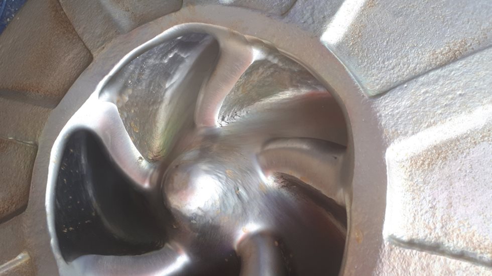
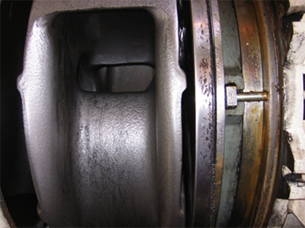
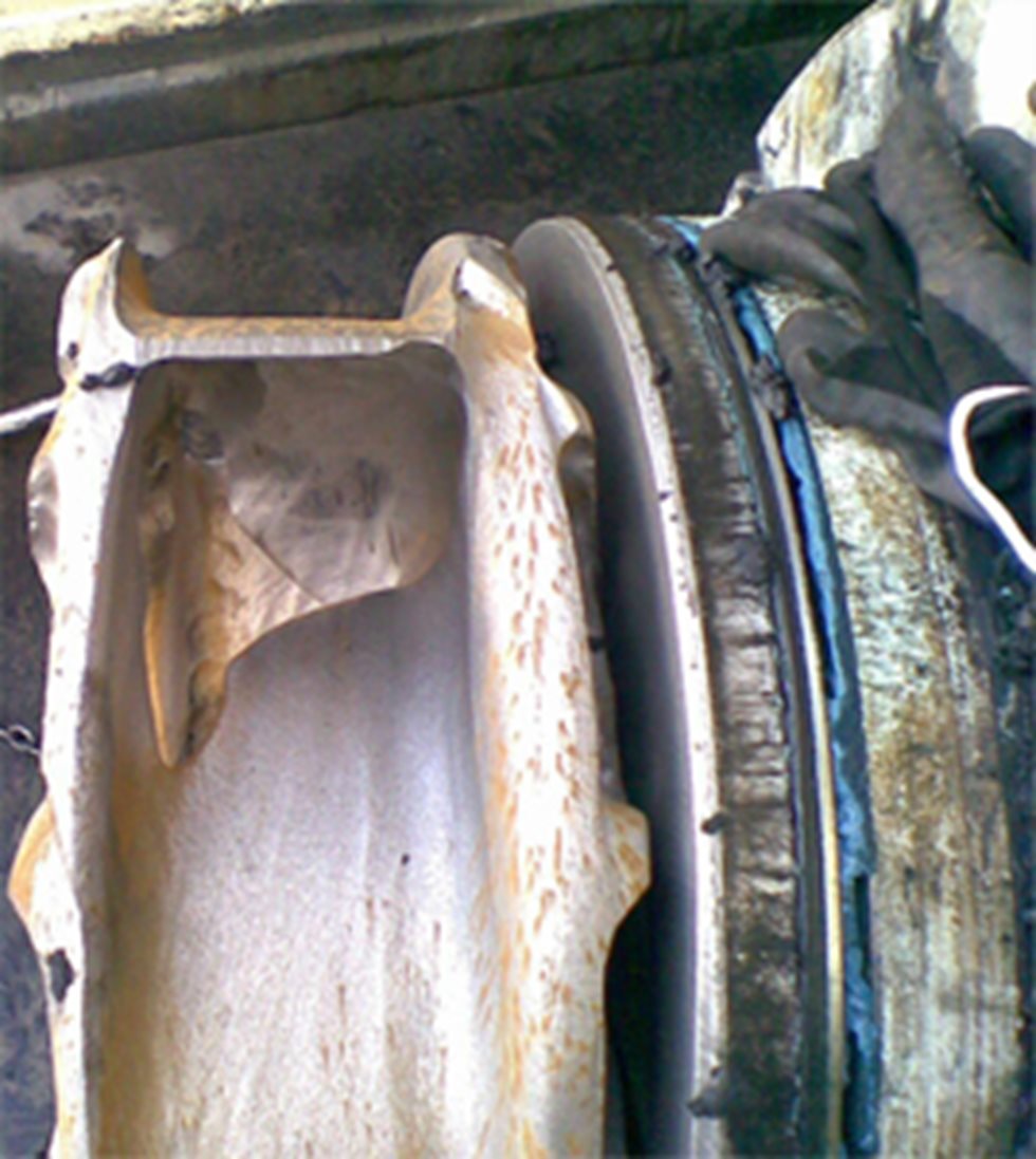
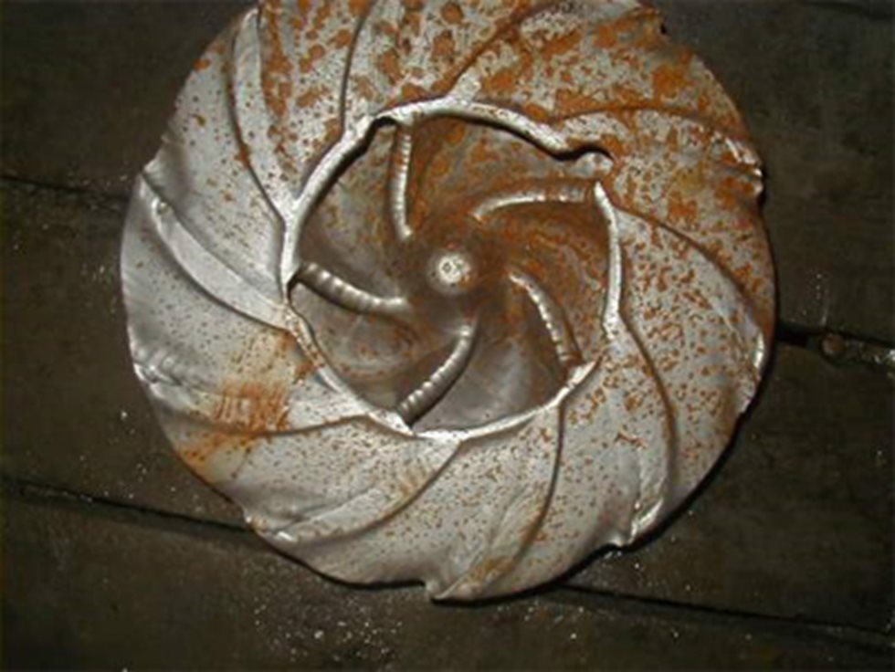
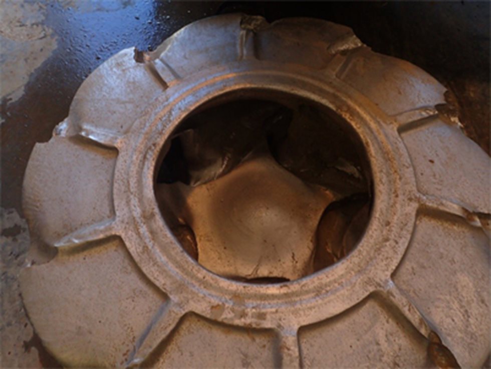
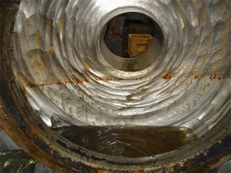
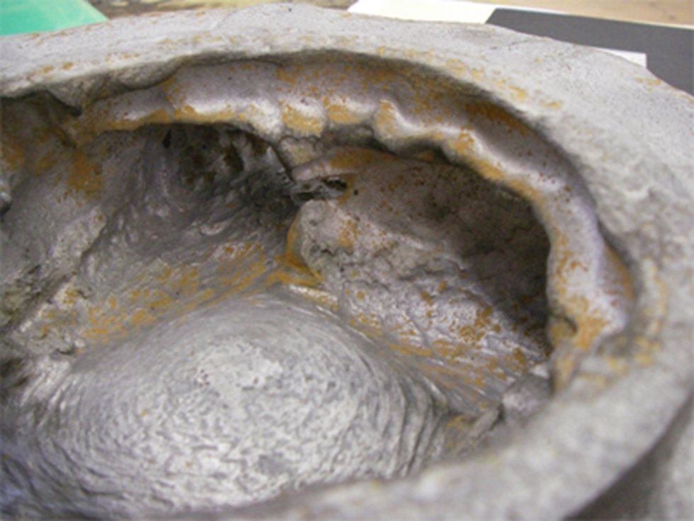
The two main mechanisms for wear of hard iron parts are impact and sliding abrasion. Sliding bed is defined by a smooth, polished surface (figure 5). Sometimes the surface develops a distinctive pattern like sand dunes (Wilson, 2006) It has been suggested that the wavelength of these dunes correlates with the particle size of the slurry (Walker, 2016)

As the particle size increases the coarse particles push through this bed and cause damage by impact. This is a much more damaging mechanism, and impact wear will result in much faster material loss. The surface will not be as smooth and may develop a frosted appearance. (Wilson, 2006)

Fine particle wear in a slurry pump.
Figure 5 - Fine particle wear

Corrosion

Parts which are exposed to corrosive liquids and abrasive solids can suffer from extreme rates of material loss. The most obvious feature of a badly corroded wear part is the colour, with the Martensite matrix turning a reddish brown colour as it is oxidized (Figure 7).

This also weakens the matrix that supports the hard carbides. These are then easily knocked out by the abrasive particles causing rapid wear. 

Fortunately, it is often possible to improve the wear life of these parts if the chemistry of the melt is altered by adding more alloying elements such as Chromium or Molybdenum.

Example image of pump worn due to corrosion.
Figure 7 - Wear and corrosion

We believe that every detail matters, the parts removed from your pump tell a story about the operating conditions. With a little experience, it is possible to diagnose the factors that cause failure. This gives you an advantage should you wish to trial new materials or geometry. The key is to keep good records and to discuss your concerns with the OEM supplier of your pumping equipment.

Bibliography:

Walker, C. I. (2016). Slurry pump selection based on particle size. Hydrotransport 20.
Wilson, A. S. (2006). Slurry Transport using centrifugal pumps. New York: Springer.

Mining Metals refining