Metso Insights Blog Aggregates blog Tips for installation and start-up of vibrating equipment
Aggregates
Sep 9, 2020

Tips for installation and start-up of vibrating equipment

Karl Simhofer
Karl Simhofer
Technical Support EMEA, Screening
Regardless of the equipment, good aggregates operation begins with proper installation. That means a proper design for the feed arrangement, and the supporting structure and supporting frame to allow full utilization of the equipment and to withstand the dynamic and static forces produced by the screen. Here we go through some questions regarding installation and start-up of vibrating equipment.
An example setup.

The feeder is the first vibrating equipment seeing the large rock fragments coming from the pit. What is important to keep in mind when designing this primary stage?

The main function of the primary vibrating feeder is to absorb the impact and deliver a controlled feed to the primary crusher. It is crucial to always keep a remaining material layer on the vibrating pan in order to absorb the impacts, protect the feeder structure, and increase the wear life.

Another important tip for protecting the primary crusher during material unloading is the design of the feeder bin. It has to be high enough to avoid leakage of material at the feeder discharge end. Another solution to consider is to install a preliminary chute before the feeder hopper to increase the distance from the discharge point to the end of its vibrating pan.

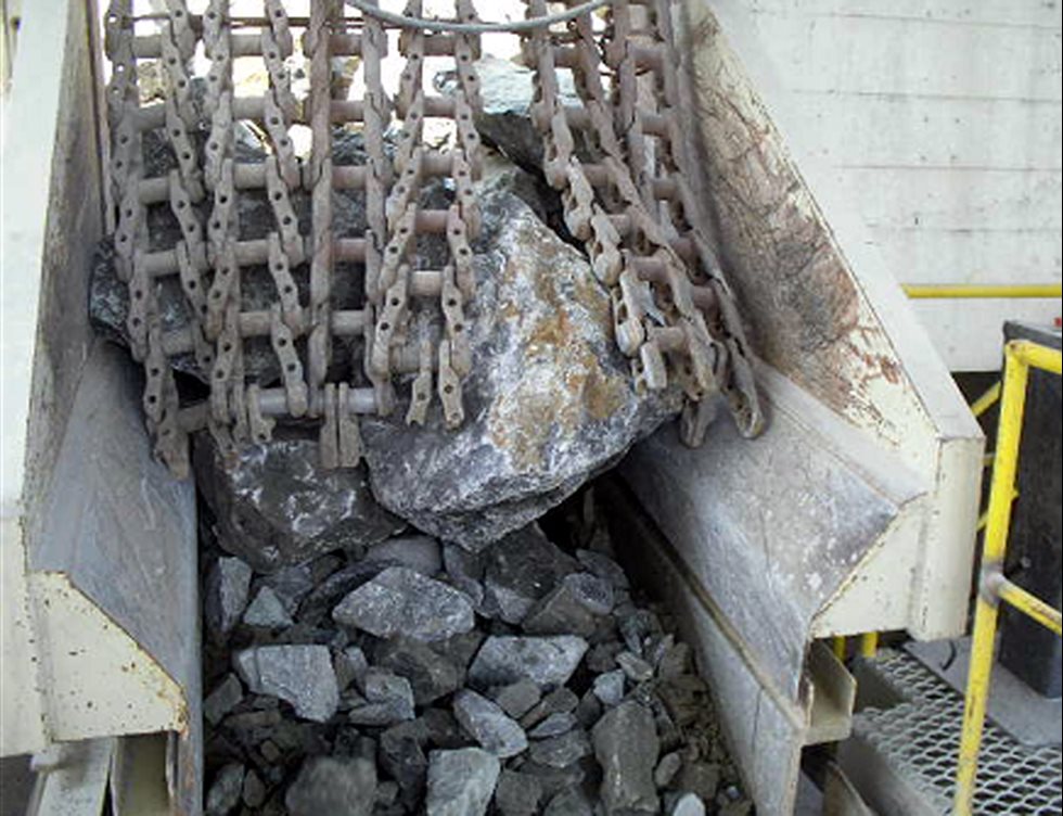
Some stones coming from this leakage can "fly over" and impact against the primary crusher at high speed, causing damage. The installation of chains, tires or other similar solutions between the feeder and the crusher can minimize this problem by slowing down the rocks unloaded by trucks.

Chains installed to slow down rocks.  the rocks

The screens are important players in the whole process of producing high-quality aggregate. Does the feed arrangement play a role in this process?

The design of the feed chute is key in improving the efficiency of classification, increasing the service life of liners and screening media, and ensuring the structural integrity of the vibrating screen.

The feed material distribution has to be along the entire width of the equipment to take full advantage of the entire screening area of the equipment. The drop height between the chute (or rock box) and the equipment liners has to be limited in order to avoid excessive impact of the material against the equipment, increase the wear life, and minimize the risk of structural failure. Also, the feed material should be located over the feedbox liners and not directly onto the screening media, to avoid premature wear of the first rows of screening panels.

Additionally, internal deflector plates can be installed in the chute whenever possible in order to reduce the speed of the material fed onto the equipment. A lower feed speed minimizes wear and improves the efficiency of classification.

By nature, the screens generate vibrations transmitted to the structure. What are the key points for a good structure design?

Screens, and especially larger screens, must have extremely strong and rigid supports! If the structure lacks sturdiness, the screen will dissipate its vibratory movement, causing the supporting structure to vibrate and either side of the screen to display differences in amplitude and phase.

The key to having a sturdy and reliable supporting frame is to take into account in the calculations the static and dynamic forces generated by the screen. Besides that, the frequency of resonance of the structure and its harmonics need to be very different from the vibrating frequency of the screen. If the speed of operation of the screen coincides with, or is close to, the natural frequency of one or more components of the structure, the vibration will be harmful for both parts. This can lead to serious personal injury and/or damage to the equipment and components.

We recommend that the structural frequency of the supporting structure or supporting frame is at least two-and-a-half times higher than the frequency of operation of the equipment.

The levels of vibrating structure should not exceed the max. allowed limit, measured at the lower part of the spring pads that are fastened to the support, in a tri-axial direction. The max. allowed limit can to be found in the GA drawings of each unit. These values are also inside our Screencheck software.

Aggregates